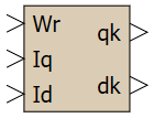
The block makes it possible to make the current control channels along the axes d and q independent of each other by generating cross-compensation signals. The value of the compensation voltages can be calculated in absolute or relative units.
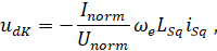
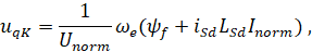
The output signals of the block are calculated by the formulas:
where:
- iSq, iSd — projections of the stator current vector on the d and q axes,
- Inorm, Unorm — normalizing values of current and voltage,
- LSd, LSd — inductances along the axes d and q,
- ψf — rotor flux linkage,
- ωe — angular speed of the stator field.
When the "Inorm" and "Unorm" properties are set to "1", the compensation voltages will be calculated in absolute units.
Прим.: For detailed description of the model see [
1, 2].
Входные порты
Parameter |
Description |
Communication line type |
Wr |
Rotor speed |
Mathematical |
Iq |
Stator current along the q-axis |
Mathematical |
Id |
Stator d-axis current |
Mathematical |
Выходные порты
Parameter |
Description |
Communication line type |
qk |
Compensation voltage along the q-axis |
Mathematical |
dk |
Compensation voltage along the d-axis |
Mathematical |
Свойства
Description |
Name |
Description |
By default |
Data type |
Stator inductance along the q-axis, H |
Lsq |
Stator inductance along the q-axis |
0.112 |
|
Stator inductance along the d-axis, H |
Lsd |
Stator inductance along the d-axis |
0.112 |
|
Number of motor poles |
Zp |
Number of motor poles |
42 |
|
Rotor flux linkage, Wb |
F |
Rotor flux linkage |
0.4 |
|
Normalizing current value, A |
Inorm |
Normalizing current value |
7 |
|
Normalizing voltage value (DC link voltage), V |
Unorm |
Normalizing voltage value (DC link voltage) |
540 |
|
Параметры
The block has no parameters.
Примеры
Examples of block application:
- Speed of permanent-field synchronous motor
- Angle of permanent-field synchronous motor