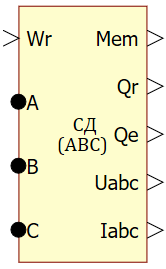
Synchronous motor (ABC system)
 |
 |
|
| in the palette | on the schematic |
The model is used together with the elements of the EC - Dynamics (ECD) 2.0 and Mechanics libraries.

- ψf — rotor flux linkage,
- Zp — the number of motor pole pairs,
- iA, iB, iC — currents of phases A, B and C,
- e1A, e1B and e1C — unit functions of the EMF shape of phases A, B and C.
The unit function of the EMF shape is a function of the field angle θe, having a unit amplitude and repeating the phase EMF in shape. The models of the motor windings for the "Star” (Y) scheme are built on the elements of the EC - Dynamics (ECD) 2.0 library.
Connection of the model to external elements is carried out as follows:
The input of the model, as a rule, is supplied with voltage signals "Uphа, Uphв, Uphс", from the model of a three-phase bridge inverter built on the elements of the EC - Dynamics (ECD) 2.0 library.
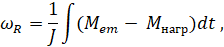
- Mem — electromagnetic torque of the motor,
- Mload — torque created by the load,
- J — the total moment of inertia applied to the rotor (the sum of the moment of inertia of the load and the moment of inertia of the rotor).
The model of the mechanical part of the electrical drive converts the signal of the electromagnetic torque into the value of the angular speed of the rotor "Wr", supplied to the corresponding input of the motor model.
Inputs
| Parameter | Description | Communication line type |
|---|---|---|
| Wr | Rotor speed | Mathematical |
Outputs
| Parameter | Description | Communication line type |
|---|---|---|
| Mem | Electromagnetic torque of the motor | Mathematical |
| Qr | Angular position of the rotor | Mathematical |
| Qe | Electrical angle of the field | Mathematical |
| Uabc | EMF in phases A, B and C | Mathematical |
| Iabc | Currents in phases A, B and C | Mathematical |
Non-directional ports
| Parameter | Description | Communication line type |
|---|---|---|
| A | Phase A input voltage | Electrical |
| B | Phase B input voltage | Electrical |
| C | Phase C input voltage | Electrical |
Properties
| Name | Parameter | Description | By default | Data type |
|---|---|---|---|---|
| Stator phase resistance, Ohm | Rs | Stator phase resistance | 16 | Вещественное |
| Stator phase inductance, H | Ls | Stator phase inductance | 0.112 | Вещественное |
| Rotor flux linkage, Wb | F | Rotor flux linkage | 0.4 | Вещественное |
| Number of motor poles | Zp | Number of motor poles | 42 | Вещественное |
| Initial electric angle of the rotor, rad. | Q0 | The initial electric angle of the rotor relative to the positive axis of the phase "A" | 0 | Вещественное |
| Shape of EMF | EMF |
Shape of the phase EMF Depending on the selected value, the shape of the motor EMF will change:
|
sine | Перечисление |
| Fourier coefficients (odd sin) | FC | Coefficients of the 1st, 3rd, 5th, 7th and 9th harmonics of the unit function of the form | [1.085, 0.043, -0.075, -0.043, -0.011] | Массив |
| Load EMF from file | read_from_ext_file | The file name of the ".dat" format is put in the "Value" column | E.dat | Имя файла |
Parameters
The block has no parameters.