Distributed SLE (Systems of Linear Equations)
This subsection describes the specialized library "SLE" and the blocks included in this library. One of the examples of rational use of the library of SLE blocks is simulating electrical network elements.
A new feature of SimInTech is the concept of building multidomain numerical models – that is, models that include the description of subsystems of different classes (electrical networks, hydraulic networks, and control systems) within a single system of equations.
Real physical networks (electrical, hydraulic), as a rule, are described in the most general form in the form of an undirected graph, in the nodes of which the equations of current (flow) balance are solved, and in the edges the conductivity coefficients between the nodes are described. At the same time, when reducing the description of a complex technical object from an undirected graph to a scheme in input-output relations, it is necessary to take into account the fact that different subsystems are effectively simulated by different numerical methods. The scheme created by the user using a graphical editor should be as close as possible to the schematic diagram of the system being described – that is, externally the system should be described by an undirected graph, and internally it should be transformable to the input-output model.
In this subsection we will consider the methodology of assembling a set of blocks, reducing the description of physical networks on the example of electrical networks, to the description of the system in input-output relations, modeling and analysis of which is performed with the help of SimInTech control systems modeling subsystem.
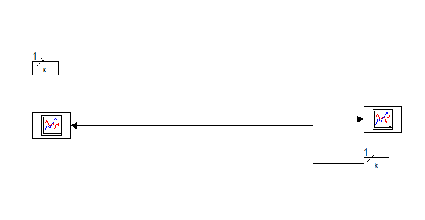
- the possibility of creating non-directional group connections;
- specialized blocks for direct work with sparse systems of linear algebraic equations (SLE).
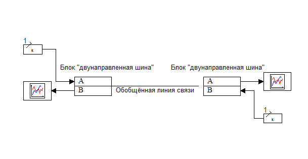
A set of specialized blocks for direct work with systems of linear algebraic equations (SLE), allows you to specify for the scheme one or more independent named sparse linear systems of the following type: A·X=B, where A is the matrix of the system coefficients; X is the result vector; B is the vector of the right-hand sides.
Using these blocks, as well as blocks for creating non-directional connections, it is possible to effectively describe physical networks within the input-output model, as well as to combine in one model the input-output representation of the model and various ways of representing the physical network (for example, the electrical network described within the single-frequency model in complex numbers and described using differential equations).
Let us consider (briefly) the method of reducing the description of electrical networks (as the simplest in description) using the method of nodal potentials [И. Влах, К. Сингхал, Машинные методы анализа и проектирования электронных схем, Радио и связь, 1988 г.; Чуа Л.О., Лин Пен-Мин, Машинный анализ электронных схем: Алгоритмы и вычислительные методы. – М.: Энергия, 1980 г.]. The nodal potential method is standard for solving electric network design problems and is used in specialized calculation programs such as SPICE. The advantages of this method include the absence of topological limitations, such as those inherent in the mesh current method.
- boundary node of the electrical network;
- node of the electric network;
- network branching;
- linear resistance;
- nonlinear resistance;
- inductance;
- capacitance;
- voltage source;
- current source.