Simulating transmission
A number of blocks of the Mechanics library are designed to simulate various kinds of gearboxes and mechanical gears with a constant gear ratio. In general, a conversion between rotary and translatory motion is possible, however, for clarity, the approach to simulating transmission will be described using the example of a gearbox, both shafts of which rotate. For generalization, the physical dimensions of the quantities will be omitted, since the described approach is applicable to both types of motion.


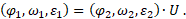
- φ1, ω1, ε1 – coordinate, speed and acceleration (motion profile) of the gearbox driving shaft
- φ2, ω2, ε2 – coordinate, speed and acceleration (motion profile) of the gearbox driven shaft
- T1 and T2 – torques on the driving and driven shafts of the gearbox, respectively
The first three ratios will hereafter be referred to as “kinematic ratios”.
In the blocks simulating transmission, the driving and driven shafts correspond to the mechanical ports by which the block is connected to other blocks of the model. The block ports can be input and output ones. Depending on the type of ports, three models are generally used.
The input port is the driving shaft
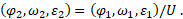

The input port is the driven shaft

Both shafts are input ports
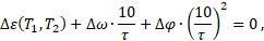
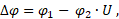
- Δφ, Δω, Δε(T1, T2) – coordinate, speed and acceleration errors
- τ – time constant for solving the nonlinear algebraic equation (NE)

If the initial coordinates, speeds or accelerations of the shafts do not satisfy the kinematic relations, then at the beginning of the simulation a hopping transient will be observed, bringing the values of these values to values that satisfy the kinematic relations. The transient time is equal to the time constant for the solution of the nonlinear algebraic equation.