About the library design code
The library is designed to simulate one-dimensional rotary or translatory motion, for example, rotation of shafts and translatory motion of the bogie system.
- force (torque or force) under which the body moves
- coordinate (turn angle or linear position)
- speed (angular or linear)
- acceleration (angular or linear)
Basic principle of simulation the dynamics of body motion
Models of mechanical systems consist of blocks connected by mechanical connection lines. The blocks of this library are submodels, within which equations describing the functioning of certain elements of mechanical systems are implemented from elementary mathematical blocks and transfer functions.
Mechanical connection lines connect the output ports of some blocks with the input ports of other blocks and are directional data buses, through which the values of the values described above are exchanged between the blocks. From the output port to the input port (in the direction of the connection line), the values of the coordinate, speed and acceleration of the body motion (body motion profile) are transmitted, and in the opposite direction – the value of the force acting on this body.
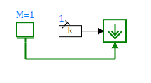
The connection line is directed from the block Mass to the block Force source, in which the mode of displaying the arrows of the input ports is enabled for clarity. A block having Massan output mechanical port transmits the values of the coordinate, speed and acceleration of the body to the connection line, and the block Force source having an input mechanical port transmits the force value to the connection line. In general, the blocks with the output mechanical ports simulate the body motion profile, and the blocks with the input mechanical ports simulate the forces and torques acting on the bodies connected to them.
Body motion under the action of several forces
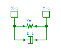
Mechanical connection lines allow branching, allowing one output port to be connected to multiple input ports. The block with the output mechanical port, which simulates the body motion, transmits the body movement profile to the connection line. The blocks with input mechanical ports calculate the values of force effects depending on the parameters of the motion profile: the spring elastic force depends on the coordinate of the body, the force of viscous friction depends on its speed, and so on. The block simulating the body motion takes the values of force actions from all the blocks connected to it and simulates the body motion under the action of the total force or torque. Thus, using the branching of a mechanical connection line, the effect of several forces or torques on one body is simulated.
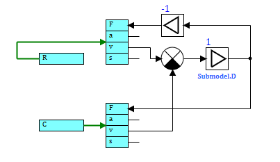
The block reads the values of linear speeds from each of its input mechanical ports "C" and "R", determines the value of the damping force and transmits it back to ports "C" and "R". At the same time, the values of the forces at different ports of these blocks have opposite signs in accordance with Newton's 3rd law. The spring model is similarly implemented.
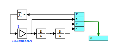
The block reads the values of the forces from the output mechanical port "R", sums them up and determines the acceleration, speed and coordinate of the body moving under the action of the total force. The calculated values are transmitted to the mechanical connection line.
Conversion of motion
A number of library blocks simulate various kinds of gearboxes and mechanical gears. The blocks having one input mechanical port and an arbitrary number of output mechanical ports (often only one) convert the motion profile and the action of external forces. For example, the output port (driven shaft) of the reduction gearbox will be transmitted with a motion profile at a proportionally lower speed than at the input port (driving shaft). And the input port (driving shaft) will be supplied with a torque value proportionally less than the torque value at the output port (driven shaft). A detailed description of the approach to simulation of gearboxes and other motion conversion elements is given on the page Simulating transmission.
Interface of mechanical connection lines
It is allowed to form user (custom) blocks having mechanical ports and used as elements of the mechanical system model. For library and user blocks to work together, user blocks must have a bi-directional data bus with identical formation rules and names of transmitted quantities.
To form a bidirectional data bus in a mechanical connection line, the Bidirectional bus (Input) and Bidirectional bus (Output) blocks are used. Both of these blocks can be used to implement both input and output mechanical ports.
- For rotary motion:
- T – torque, Nm
- Fi – turn angle, rad
- w – angular speed, rad/s
- eps – angular acceleration, rad/s2
- For translatory motion:
- F – force, N
- s – linear position, m
- v – linear speed, m/s
- a – linear acceleration, m/s2
The Bidirectional bus (Input) and Bidirectional bus (Output) blocks on the output rotary ports shall have an output "T" port and input "fi", "w", and "eps" ports. The Bidirectional bus (Input) and Bidirectional bus (Output) blocks on the output translatory ports shall have an output port "F" and input ports "s", "v", and "a". At the input ports, the direction of the ports of the Bidirectional bus (Input) and Bidirectional bus (Output) blocks must be reversed.
A detailed description of the user (custom) block development is provided on the page .