BDCM key selector block

 
в палитре на схеме

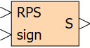
The block implements a logical algorithm for selecting the inverter keys depending on the position of the rotor and the sign of the specified torque.

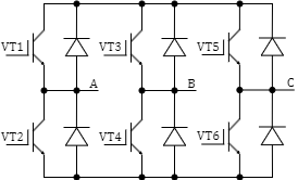
How the output signals of the block and the keys of the three-phase inverter is matching each other, is illustrated in the figure (Figure 1).

Рисунок 1. Distribution of output signals

Key selection signals are generated by the model depending on the value of the “sign” signal and signals from the RPS in accordance with the table (Table 1).

Таблица 1. Signal-key matching
Field angle 0...30° 30°...90° 90°...150° 150°...210° 210°...270° 270°...330° 330°...0
RPS (3 2 1) 0 0 1 0 1 1 0 1 0 1 1 0 1 0 0 1 0 1 0 0 1
sign = 0

(M > 0)

- S2 S2 - S1 S1 -
S3 S3 - S4 S4 - S3
S6 - S5 S5 - S6 S6
sign = 1

(M < 0)

- S1 S1 - S2 S2 -
S4 S4 - S3 S3 - S4
S5 - S6 S6 - S5 S5
Прим.: For detailed description of the model see [1, 2].

Входные порты

Name Description Communication line type
RPS Three-channel signal from the rotor position sensor Mathematical
signature Torque sign input Mathematical

Выходные порты

Name Description Communication line type
S 6-channel signal for selection of the inverter keys Mathematical

Свойства

The block has no properties.

Параметры

The block has no parameters.

Примеры

Examples of block application:
  • Position of the BDCM