PWM
|
|
|
|
| in the palette | on the schematic |
The block is used in the BDCM and implements PWM modulation inside the pulses coming from the selector of the inverter keys.
The figure below explains the dependency between the parameters of the triangular PWM reference signal and the values set in the block properties (Figure 1).

Figure 1. PWM triangular reference signal parameters
The six-channel signal "PWM" manages the IGBT bridge keys. The distribution of the output signals (VT1...VT6) when controlling the half-bridges of the three-phase inverter is shown in the figure (Figure 2).
The block allows you to implement three types of PWM modulation:
PWM 1 (Figure 3):
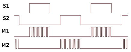
Figure 3. Type of PWM signals for the "PWM - 1" circuit
- It can be used with sufficiently large winding inductances.
- The reactive currents are closed through the inverter power supply.
PWM 2 (Figure 4):
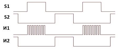
Figure 4. Type of PWM signals for the "PWM - 2" circuit
- Provides minimum current pulsations in the motor windings.
- Reactive currents are closed through the motor windings and inverter diodes.
- It provides a minimum of losses in the lower keys of the inverter.
PWM 3 (Figure 5):
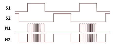
Figure 5. Type of PWM signals for the "PWM - 3" circuit
- It can be used for bootstrap power supply of inverter key drivers.
- Provides minimum current pulsations in the motor windings.
- Reactive currents are closed through the motor windings and the inverter keys.
Inputs
| Parameter | Description | Communication line type |
|---|---|---|
| U | Modulated signal | Mathematical |
| S | Six-channel signal input from BDCM key selector | Mathematical |
Outputs
| Name | Description | Communication line type |
|---|---|---|
| PWM | Six-channel control signal of the IGBT bridge keys | Mathematical |
Properties
| Name | Name | Description | Default value | Data type |
|---|---|---|---|---|
| Maximum value of the reference signal, ([V] or [r.u.]) | max | Maximum PWM reference triangle value | 1 | Вещественное |
| Minimum reference signal value | min | Minimum PWM reference triangle value | -0.0037 | Вещественное |
| Period, s | Tpwm | PWM period | 5E-5 | Вещественное |
| Protective pause time, s | tz | Inverter rack keys ON protection pause time | 1E-6 | Вещественное |
| PWM diagram | mode | PWM type selection The possible values are:
|
PWM 1 | Перечисление |
Parameters
The block has no parameters.
Examples
Examples of block application:
- Position of the BDCM