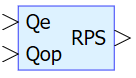
The block is used in BDCM simulation and allows you to determine the electrical angle of the rotor with an accuracy of 60°. The rotor position sensor has three channels. Each channel generates a pulse corresponding to half of the period for one period of the electric angle, while the pulses of the channels are shifted by a third of the period (120 electric degrees).
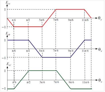
The trapezoidal shape of phase EMF depending on the electric angle of the rotor is shown in the figure (Figure 1):
Figure 1. Trapezoidal shape of phase EMF
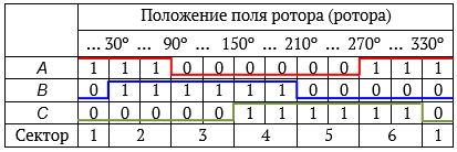
The matching of the signals in the channels to the electric angle is explained by the following table (Figure 2):
Figure 2. Trapezoidal shape of phase EMF
Inputs
Parameter
Description
Communication line type
Qe
Electric angle
Mathematical
Qop
Advance angle (sometimes used when controlling the rotor position sensor, its value is usually changed depending on the rotor speed)