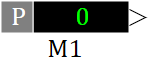
Sensor
 |
 |
| Vectorized | C | |
in the palette |
on the schematic |
The block is similar to the Input contact block, with the addition of the measured value display. It implements reading of the variable, transferring it to the block output, as well as displaying the value of the variable on the schematic window in a user-defined format. In the local debugging mode it is equivalent to a constant. In remote debugging, the block reads the variable from the executive system.
Properties
- Default value – value at the block output, can be a vector.
- Contact type – data type of output variable when generating code for full-scale model.
- Contact name – name of a variable read by the block.
- Variable name format – the rule of forming the name of the variable read by the block.
- Add to signal database – checkbox (flag) indicating whether it is necessary to create this variable in the signals base of the system.
- Request for name from the database – request from the database to form the name of the read variable.
- Functional plan – name of the diagram file to which it is necessary to go when double-clicking on the object.
- Debugging component – name of the component that will be set when switching to another diagram in the debugging mode.
Properties that affect only the appearance of the block:
- Sensor type – a symbol or line that explains the type of value measured by the sensor and is used on the left side of the sensor image.
- Total digits – a number that determines the total number of digits (before and after the decimal point) when displaying sensor readings.
- Number of decimal places – a number that specifies the number of digits after the decimal point when displaying sensor readings.
- Number format – checkbox (flag) that specifies in what format to output the value of the measured value.
- Sensor description – text in the user format (arbitrary), describing the sensor, measured value, etc. It is output by default in the block caption.
Parameters
- Sensor value.
Note:
block can be used to generate C-code for an external target system.