Algorithm output
 |
 |
| Vector | C | |
| in the palette | on the schematic |
The block records signal values (data recording) to the local list of project signals or to the list of signals of the connected database. When you double-click on the block, the editor of the list of recorded variables appears:
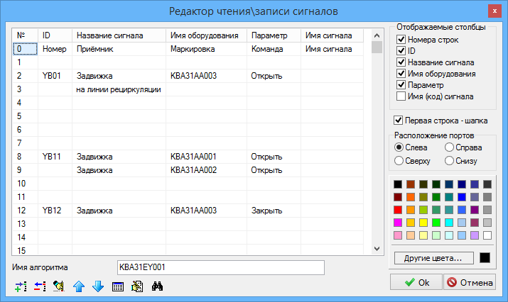
The name of a variable is set in the Signal name field. Each input of the block corresponds to its own signal.
The name of a variable is set in the Signal name field. Each input of the block corresponds to its own signal.
Assigning table fields
- No. - the serial number of the signal (and, accordingly, the input of the block) is set;
- ID - signal (input) identifier;
- Receiver - a description of the "destination" of the signal (where the signal goes);
- Marking - the marking of the signal (or signal receiver);
- Command - designation or name of the command. It is used when creating algorithms for generating commands to control units of valves, motors, etc.
- Signal name - the name of the variable recorded in the database.
Properties
- Auto reset.
- Calculate with a step delay.
- Translate to the executive system.
- Use the signal itself as the debug output value.
Parameters
none