Cross-linking compensation block for AM


in the palette on the schematic

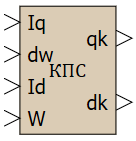
The block makes it possible to make the current control channels along the axes d and q independent of each other by generating cross-compensation signals. The values of compensation signals are calculated in relative or absolute units [V].

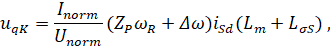
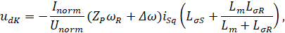
The output signals of the block are calculated by the formulas:


where:
  • iSq, iSd — projections of the stator current vector on the d and q axes,
  • Inorm, Unorm — normalizing values of current and voltage,
  • ωR — stator angular speed,
  • Zp — the number of motor pole pairs,
  • Δω — angular field slip velocity,
  • Lm — the magnetizing inductance,
  • LσS, LσR — stator and rotor leakage inductances.
Note:
A more detailed description of the model is presented in [1, 2].

Inputs

Parameter Description Communication line type
Iq Stator current along the q-axis Mathematical
dw Field slip velocity Mathematical
Id Stator d-axis current Mathematical
W Rotor speed Mathematical

Outputs

Parameter Description Communication line type
qk Compensation voltage along the q-axis Mathematical
dk Compensation voltage along the d-axis Mathematical

Properties

Title Parameter Description By default Data type
Magnetizing inductance, H Lm Magnetizing inductance 0.086 Вещественное
Rotor leakage inductance, H dLr Rotor leakage inductance 0.0025 Вещественное
Stator leakage inductance, H dLs Stator leakage inductance 0.0016 Вещественное
Number of pole pairs Zp Number of pole pairs 1 Вещественное
Normalizing current value, A Inorm Normalizing current value 1 Вещественное
Normalizing voltage (DC link voltage), V Unorm Normalizing voltage (DC link voltage) 1.73 Вещественное

Parameters

The block has no parameters.

Examples

Examples of block application:
  • AM position
  • AM speed
  • AM speed in relative units
  • Speed of permanent-field synchronous motor
  • Angle of permanent-field synchronous motor

Literature