Rotor flux angle calculation block (for systems with direct orientation by flux). The block calculates the sine and cosine of the rotor flux angle in a fixed coordinate system (relative to axis A).
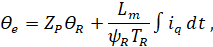
The rotor flux angle θe in a fixed coordinate system is calculated using the following formula:
where:
θe — rotor electrical angle,
θR — rotor angle,
Zp — the number of motor pole pairs,
ψR — rotor flux linkage,
TR = (Lm + LσR)/RR — rotor time constant,
Lm — the magnetizing inductance,
LσR — rotor leakage inductance,
RR — rotor resistance,
iSq — projection of the stator current vector on the q-axis.
The angle measured with respect to the positive axis of phase A is considered positive, counterclockwise.
Note:
A more detailed description of the model is presented in [1, 2].
Inputs
Parameter
Description
Communication line type
Iq
Stator current along q-axis
Mathematical
Qr
Rotor angle
Mathematical
F
Rotor flux
Mathematical
Outputs
Parameter
Description
Communication line type
SinQ
Sine of the rotor flux angle in a fixed coordinate system ABC relative to axis A
Mathematical
CosQ
Cosine of the rotor flux angle in a fixed coordinate system ABC relative to axis A