The block implements a mathematical model of the Smith predictor.
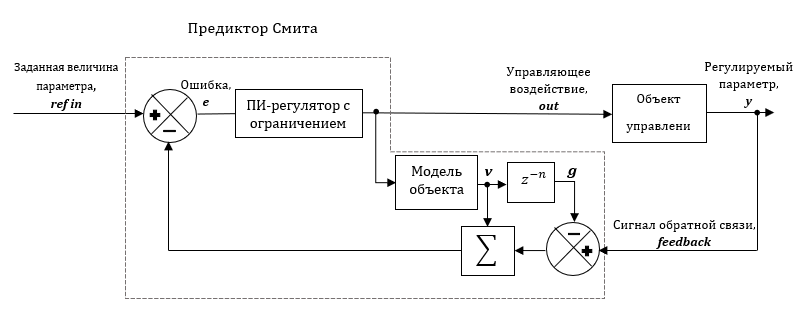
Smith predictor shown in figure (Figure 1) consists of a main regulator and a predictor structure. The predictor part consists of a no-delay object model and a delay model.
Figure 1. Structural diagram of the closed-loop system with Smith predictor.
The output signal of the PI controller (port out of the block) is applied to the control object and to the internal model of the controller. The PI controller primarily controls the model, rather than the control object, through the summator. The signal g must match the measured signal of the regulated variable y. The y and g signals are compared to produce an error signal that includes errors from both the interference and the model. They are added to the v signal from the object model to feed the feedback signal to the PI controller block.
The transfer function of the system has the form:
where WO, WPI(z), WMO(z) are the transfer functions of the control object, PI controller and object model, respectively.
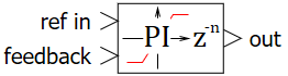
Input ports
ref in – setting action signal;
feedback – feedback signal.
Output ports
out – controlling action signal.
Properties
PI controller with a limitation
Proportional term – gain value of the P-term;
Integral term – gain value of the I-term;
Sampling period – block calculation sampling period;