Sliding mode regulator
 |
 |
| Vectorized | |
in the palette |
on the schematic |
The block implements the mathematical model of a discrete sliding mode regulator based on hysteresis.
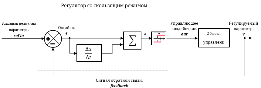
Sliding mode based control is based on the principle of switching between two modes for nonlinear systems. The regulator includes blocks that define a sliding surface that represents the required stable dynamics and a control law that ensures the mode of reaching the sliding surface and the sliding mode.

where e – the error signal, Δe⁄Δt– the derivative of the error.
A homogeneous differential equation having a single solution is obtained when s = 0. Thus the error will reach zero with an appropriate control law that keeps the trajectory on the sliding surface. A relay with hysteresis is used as the control law. Thus, the output signal of the controller, is selected from two possible actions Y1 and Y2, the lower and upper values of the function, respectively.
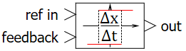
Input ports
- ref in – setting action signal;
- feedback – feedback signal.
Output ports
- out – controlling action signal.
Properties
- Relay ambiguous (hysteresis)
- Upper switching limit – the maximum value of the input quantity at which the value at the output is equal to the upper value;
- Upper value of the function – the maximum value at the block output;
- Lower switching limit – the minimum value of the input signal, at which the value at the output is equal to the lower value;
- Lower value of the function – the minimum value at the block output;
- Discrete derivative
- Initial conditions of discrete derivative – vector of initial values yi(0) of the block output signal;
- Sampling period – block calculation sampling period.
Parameters
None