State feedback controller
 |
 |
| Vectorized | |
in the palette |
on the schematic |
The block implements a mathematical model of a discrete state feedback controller.
The controller is used to control linear systems in control loops equipped with a feedback link.
The block is a submodel, the structural diagram of which as part of the closed-loop system is shown in the figure (Figure 1):
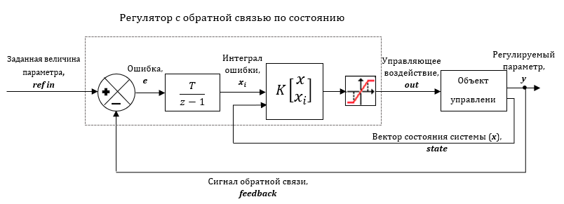
Figure 1. Structural diagram of the system equipped with a state feedback controller.
The output signal of the block is determined by the following ratio:

where K is the controller feedback matrix, xe is the extended system state vector that is equal to:

The error integral, xi, is an additional state that provides a zero steady-state error for a closed-loop system.
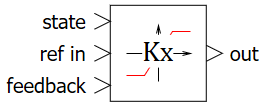
Input ports
- state – measured or estimated state vector of the system;
- ref in – setting action signal;
- feedback – feedback signal.
Output ports
- out – controlling action signal.
Properties
- Matrix of gain coefficients – a preset matrix of the controller feedback;
- Minimum value – the minimum value of the output;
- Maximum value – maximum output value;
- Sampling period – block calculation sampling period.
Parameters
None