Bevel clutch
 |
 |
| C | |
| in the palette | on the schematic |
The block in designed to simulate a bevel clutch connecting two rotating bodies. The block allows you to simulate a friction disk package with an arbitrary number of contact surfaces. The torque transfer may be applied in both directions (bidirectional) or in a predetermined (from one port to another). In the second case, torque will be transmitted only if the angular speed at the transmitting port is greater than or equal to the angular speed at the receiving port.

where ωB, ωF – angular speeds at ports "B" and "F", respectively, rad/s
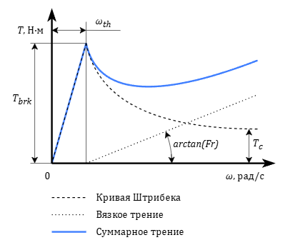
Defining the friction curve is possible in two ways: the Stribeck curve and the tabulated curve.
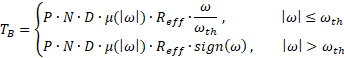
Stribek curve
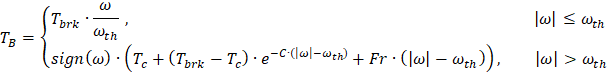

- TB and TF – torques applied to ports "B" and "F", respectively, Nm
- Tbrk – breakaway friction torque, Nm
- Tc – dry (coulomb) friction torque, Nm
- ωth – breakaway angular speed, rad/s
- C – damp ratio, s/rad
- Fr – coefficient of internal friction, Nm·s/rad
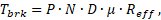
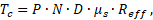
- P – pressing force, N
- N – number of contact surfaces
- D – wear factor of friction surfaces valued from 1 to 0, where 1 corresponds to zero wear
- μ – breakaway friction factor
- μs – dry (coulomb) friction factor
- Reff – effective radius of the disk in meters which is set explicitly or calculated by the formula:
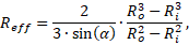
- Ro – outer disk radius, m
- Ri – inner disk radius, m
- α – bevel angle, rad
Tabulated curve
Using this method the friction factor is defined by interpolating a given table. If the slip speed exceeds the value specified in the table, extrapolation is not carried out.

where μ(|ω|) – friction factor value obtained as a result of interpolation.
Inputs
| Name | Description | Connection line type |
|---|---|---|
| N | Number of contact surfaces | Mathematical |
| V | Port for connecting the drive shaft (base) | Rotary mechanics |
| F | Port for connecting the driven shaft (following) | Rotary mechanics |
Outputs
None.
Properties
| Name | Parameter | Description | By default | Data type |
|---|---|---|---|---|
| Type of torque transmission | Dir | Type of torque transmission The possible values are: "Bidirectional", "Port B to Port F", "Port F to Port B" | Bidirectional | Перечисление |
| Friction | A group of properties that define the friction parameters | |||
| Friction model | MType | Friction model type The possible values are: "Stribek curve", "Tabulated curve” | Stribek curve | Перечисление |
| Breakaway angular speed, rad/s | Wth | The threshold value of the angular speed below which the value of the friction force is reduced to achieve the stability of the numerical solution. The property is available when selecting the model defining method as "Stribek curve" | 0.01 | Вещественное |
| Breakaway friction factor | Mu | Breakaway friction factor. The property is available when selecting the model defining method as "Stribek curve" | 0.3 | Вещественное |
| Dry (coulomb) friction factor | Mus | Dry (coulomb) friction factor. The property is available when selecting the model defining method as "Stribek curve" | 0.15 | Вещественное |
| Damp ratio, s/rad | C | Damp ratio. The property is available when selecting the model defining method as "Stribek curve" | 1 | Вещественное |
| Coefficient of internal friction, Nm·s/rad | Fr | Coefficient of internal friction. The property is available when selecting the model defining method as "Stribek curve" | 0 | Вещественное |
| Number of contact surfaces | N | Number of contact surfaces | 1 | Целое |
| Wear factor | D | Wear factor in the range [0, 1] | 1 | Вещественное |
| Array of speeds, rad/s | Wx | Array of slip speed values. The property is available when selecting the model defining method as "Tabulated curve" | [0 , 0.1 , 0.2 , 0.3 , 0.4 , 0.5 , 1 , 2 , 5] | Массив |
| Array of friction factors | My | Array of friction factor values. The property is available when selecting the model defining method as "Tabulated curve" | [0.29 , 0.28 , 0.26 , 0.22 , 0.21 , 0.2 , 0.2 , 0.19 , 0.19] | Массив |
| Maximum pressing force, N | Pth | The maximum pressing force limiting the value of defining pressing force | 200 | Вещественное |
| Geometry | A group of properties that define the geometric parameters of surfaces | |||
| Disk geometry defining method | R_type | Disk geometry defining method. The possible values are: "Outer and inner radii", "Effective radius" | Outer and inner radii | Перечисление |
| Outer disk radius, m | Ro | Outer disk radius. The property is available when selecting the method of defining the disk geometry as "Outer and inner radii" | 15 | Вещественное |
| Inner disk radius, m | Ri | Inner disk radius. The property is available when selecting the method of defining the disk geometry as "Outer and inner radii" | 0 | Вещественное |
| Bevel angle, deg | Alfa | Bevel angle. The property is available when selecting the method of defining the disk geometry as "Outer and inner radii" | 10 | Вещественное |
| Effective disk radius, m | Reff | Effective disk radius. Changing the property is only possible when choosing the method of disk geometry defining as the "Effective radius", otherwise the property is displayed in the "Read-only" mode and is for reference only | 57.5877 | Вещественное |
Parameters
| Name | Parameter | Description | Data type |
|---|---|---|---|
| Torque, Nm | T | Torque transmitted to port "F" | Вещественное |
| Angular speed differential, rad/s | W | Relative angular speed | Вещественное |
Examples
Literature
- Richard Stribeck: Die wesentlichen Eigenschaften der Gleit- und Rollenlager, Z. Verein. Deut. Ing. Vol. 46 Seite 38ff. 1341–1348 (1902).