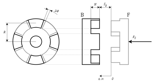
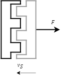
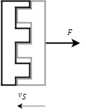
The block is designed to simulate a cam clutch consisting of two toothed disks (half-couplings) and a control mechanism (CG) moving one of the disks to engage and disengage the half-couplings. The diagram of the clutch is shown in the figure (Figure 1).
Figure 1. Cam clutch diagram
The diagram shows the half-couplings "B" and "F" and the force that acts on the side of the control mechanism on the half-coupling, i.e. FS. The force with which the half-coupling acts on the control mechanism is determined by the formula:
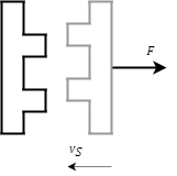
The zero position of the control mechanism corresponds to the complete disengagement of the half-couplings with a clearance Sg. The increase in the linear position of the control mechanism corresponds to the approach of the half-couplings (Figure 2).
Figure 2. Diagram of the approach of the half-couplings
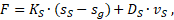
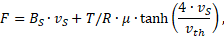
The approach of the half-couplings is characterized by a friction force F, N applied to the control mechanism and zero torque:
where:
BS – friction factor of the control mechanism, N·s/m
vS – speed of the control mechanism, m/s
When the zero clearance between the half-couplings is reached, there is either contact of the tooth tips (Figure 3) or further approach depending on whether there is an angular overlap of the teeth.
Figure 3. Position of the half-couplings when the zero clearance between the half-couplings is reached and there is an angular overlap of the teeth
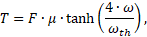
The contact of the tooth tips is characterized by the pressure force F, N applied to the control mechanism and the friction torque T, Nm applied to the half-couplings:
where:
SS – position of the control mechanism, m
Sg – clearance at full disengagement, m
KS – stiffness factor at stop, N/m
DS – damping factor at stop, N·sс/m
μ – friction factor between the teeth
ω – relative angular speed of the half-couplings, rad/s
ωth – angular speed threshold value used to achieve the stability of the numerical solution by reducing the friction force at a slip speed below the threshold, rad/s
The half-couplings will remain in contact with the tops of the teeth until the teeth fall into the grooves of the half-couplings. After that, the approach of the half-couplings will continue (Figure 4).
Figure 4. Position of the half-couplings in the state of contact of the tooth tips
The approach of the half-couplings is characterized by a friction force F, N applied to the control mechanism and zero torque:
When the overlap of the teeth is more than the minimum overlap, it becomes possible to engage the half-couplings (contact of the lateral surfaces of the teeth) (Figure 5). If at the moment of contact the overlap is less than the minimum, the couplings will continue relative rotation disengaged, and a disengaging force will be applied to the control mechanism.
Figure 5. Position of the half-couplings in the state of contact of the lateral surfaces of the teeth
The engagement of the half-couplings is characterized by the friction force F, N applied to the control mechanism and the torque of the pressure forces of the teeth T, Nm applied to the half-couplings:
where:
R – average radius of teeth (distance to the axis of rotation), m
vth – linear speed threshold value used to achieve the stability of the numerical solution by reducing the friction force at a slip speed below the threshold, rad/s
K – stiffness factor of the teeth, Nm/rad
D – damping factor of the teeth, Nm·s/rad
φ – angular deformation of the teeth (the difference in the angular positions of the half-couplings), rad
ω – relative angular speed of the half-couplings, rad/s
When meshing to the full height of the teeth, the tops of the teeth rest against the bases of the grooves (Figure 6).
Figure 6. Position of the half-couplings when meshing to the full height of the teeth
The contact of the tooth tips with the groove bases is characterized by the pressure force F, N applied to the control mechanism:
where H – height of the teeth, m
The contact of the lateral surfaces of the teeth can occur both before and after the contact of the tops of the teeth with the bases of the grooves, depending on the properties of the clutch and the blocks connected to it.
Optionally, when the clutch is fully disengaged (at the zero position of the control mechanism), it is possible to simulate the contact of the control mechanism with the stop, which does not allow to increase the clearance by more than the value Sg.
Inputs
Name
Description
Connection line type
S
Port for connecting the control mechanism
Translatory mechanics
B
Port for connecting the drive shaft (base)
Rotary mechanics
F
Port for connecting the driven shaft (following)
Rotary mechanics
Outputs
None.
Properties
Name
Parameter
Description
By default
Data type
Teeth
A group of properties that define the teeth parameters