Harmonic Analyzer
 |
 |
| Vectorized | |
in the palette |
on the schematic |
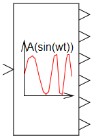
The "Harmonic Analyzer" unit is a ready-made model that implements an algorithm for direct calculation of the frequency response of an arbitrary system when a test sinusoidal signal with a discretely varying frequency and a predetermined amplitude of oscillations is applied to its input. It allows to obtain integral frequency characteristics of arbitrary nonlinear systems and to estimate the amplitude-frequency response characteristic of the system at different amplitudes of the input signal.
Working with the "Harmonic Analyzer" unit
The first output of the "Harmonic Analyzer" unit is the source of the test sinusoidal signal, therefore it must be connected to the input of the investigated unit (system).
To obtain the results of the unit operation, it is necessary to run the circuit for simulation. Upon completion of the frequency response calculation, the unit will independently generate a command to stop the simulation. The time required to calculate the amplitude-frequency response characteristic is calculated automatically, depending on the properties of the block, so the final modeling time of the system in the model calculation parameters window must be set by a knowingly larger number than may be necessary for this.
Input Ports
| Parameter name | Description | Communication line type |
|---|---|---|
| f(i*w*t) | Input to which the test system output must be connected | Mathematical |
Output Ports
| Parameter | Description | Communication line type |
|---|---|---|
| i*w*t | Test harmonic signal to be applied to the input of the system under study | Mathematical |
| Frequency | Current circular frequency of test harmonic signal | Mathematical |
| A(w*t) | Current value of the amplitude-frequency response characteristic of the system under study | Mathematical |
| F(w*t) | Current value of the circuit phase response of the system under study | Mathematical |
| re(w*t) | Current value of the real part of the amplitude-phase frequency response of the system under study | Mathematical |
| im(w*t) | Current value of the imaginary part of the amplitude-phase frequency response characteristic | Mathematical |
Properties
| Title | Parameter | Description | By default | Data type |
|---|---|---|---|---|
| Number of AFC intervals | nfpoints | Number of sections with discretely varying frequency | 500 | Real |
| Minimum frequency | fmin | Initial frequency of test harmonic signal | 0.1 | Real |
| Maximum frequency | fmax | Final frequency of test harmonic signal | 100 | Real |
| Unit of frequency | freqdim | Selection of unit of frequency ("1/s", "Hz") | Hz | Enumeration |
| Law of frequency change | freqarraytype | Selection of the frequency change law ("Linear", "Logarithmic") | Logarithmic | Enumeration |
| Number of stabilization periods | nstab | Number of harmonic test signal periods required to measure AFC at each frequency | 6 | Real |
| Coefficient of increase in the number of periods with a frequency of | kfstab | The value of the coefficient of increase in the number of periods with a frequency of | 0.5 | Real |
| Signal amplitude | Ampl | Test harmonic signal amplitude | 1 | Real |
| Unit of PFC | ffcdim | Selecting the dimension of the phase-frequency response characteristic ("Radians", "Degrees") | Degrees | Enumeration |
| Unit of AFC | afcdim | Selection of the amplitude-frequency response characteristic unit ("Absolute", "dB (20*lg(x))", "dB (10*lg(x))") | dB (20*lg(x)) | Enumeration |
| Minimum of AFC for logarithm | min_af | Minimum AFC value for logarithm | 1E-20 | Real |
| Frequency output method | freqouttype | Allows you to choose at what point in time to change the frequency value on the output port "Frequency" ("At the time of measurement start", "Simultaneously with AFC and PFC") | At the start of the measurement | Enumeration |
Parameters
The block has no parameters.
Examples
Examples of block application: