Tachogenerator
 |
 |
| C | |
| in the palette | on the schematic |
The block is designed to simulate a tachogenerator that converts the angular speed of the shaft rotation into an electric voltage, which is determined by the formula:
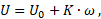
where:
- U – steady state voltage, V
- U0 – constant voltage (shift), V
- K – sensor sensitivity, V·s/rad
- ω – angular speed of the shaft rotation, rad/s
The block limits the voltage to the minimum and maximum allowable values.
The block optionally allows you to simulate the inertia of the electrical part of the tachogenerator by adding an aperiodic block with the transfer function to the model:
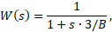
where B is the cutoff frequency, Hz.
The positive voltage direction is taken as the direction from port "+" to port "-".
Inputs
| Name | Description | Connection line type |
|---|---|---|
| + | Electrical signal port | Electrical |
| - | Electrical signal port | Electrical |
| R | Port for connecting a conditionally moving shaft (rotor) | Rotary mechanics |
Outputs
None.
Properties
| Name | Parameter | Description | By default | Data type |
|---|---|---|---|---|
| Sensitivity, V·s/rad | K | Sensor sensitivity | 0.4 | Вещественное |
| Constant output shift, V | U0 | Constant voltage (shift), V | 0 | Вещественное |
| Minimum output value, V | Umin | Minimum value of constant voltage (shift) | -2.1 | Вещественное |
| Maximum output value, V | Umax | Maximum value of constant voltage (shift) | 2.1 | Вещественное |
| Consider inertia | IsBand | Allows you to take into account the inertia of the system | Yes | Двоичное |
| Cutoff frequency, Hz | V | Cutoff frequency. The property is available when the "Consider inertia" property is activated | 800 | Вещественное |
Parameters
| Name | Parameter | Description | Data type |
|---|---|---|---|
| Voltage, V | U | Steady state voltage | Вещественное |
| Angular speed, rad/s | W | Shaft angular speed | Вещественное |
Examples
Examples of block application: