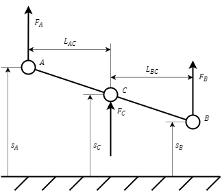
The block is designed to simulate a one-dimensional movement of the lever connecting three translatory moving bodies. The diagram of the lever is shown in the figure (Figure 1).
Figure 1. Lever diagram
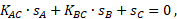
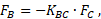
The block is described by the equations of motion valid at a small angle of inclination of the lever:
where:
sA, sB and sC – positions of bodies at ports "A", "B" and "C", respectively, m
FA, FB and FC – forces at ports "A", "B" and "C" respectively, N
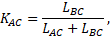
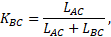
KAC and KBC – coefficients that are calculated by the formulas:
where LAC and LBC are the lever arm lengths, m.
Positive reference directions of positions and forces are shown in the figure (Figure 1).
Ports
Name
Description
Connection line type
A
Port for connecting model blocks. The port is input if specified in the"Input Ports" property, otherwise this port is output
Translatory mechanics
B
Port for connecting model blocks. The port is input if specified in the"Input Ports" property, otherwise this port is output
Translatory mechanics
C
Port for connecting model blocks. The port is input if specified in the"Input Ports" property, otherwise this port is output
Translatory mechanics
Properties
Name
Parameter
Description
By default
Data type
Input ports
mod_type
Allows you to specify the input ports. The possible values are: "A and B", "A and C", "B and C" and "A, B and C"
Time constant for solving the nonlinear algebraic equation, s
Tau
The time constant for solving the nonlinear algebraic equation. Used to solve the coupling equation. The property is available when selecting the input ports "A, B and C"