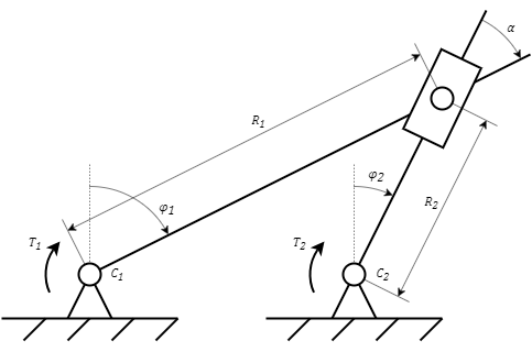
The block is designed to simulate the rotary motion of two bodies having a hinge joint. In combination with the block Hinge-slider joint,it allows you to simulate the mechanism shown in the figure (Figure 1).
Figure 1. Hinge joint
The block allows you to simulate mechanisms in which the fastening planes of the hinges C1 and C 2 are parallel or perpendicular (fastening to a vertical plane). The figure (Figure 1) shows a mechanism with a parallel arrangement of the hinge attachment planes. In case of arbitrary arrangement of the hinge attachment planes, this should be taken into account when determining the angle α.
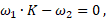
The block is described by the following equations:
where:
ω1 and ω2 – angular speeds at ports "C1" and "C2", respectively, rad/s
εC and εR – angular accelerations at ports "C1" and "C2", respectively, rad/s2
T1 and T2 – torques applied to ports "C1" and "C2", respectively, Nm
K – coupling coefficient
R1/R2 – ratio of distances between hinges (Figure 1), m
α – angle between the bodies, rad. As a rule, it is determined by the difference between the angles φ1 and φ2 (Figure 1)
The block determines the torques T1 and T2 by solving the coupling equation.
Inputs
Name
Description
Connection line type
C1
Port for connecting model blocks to a rotating body
Rotary mechanics
C2
Port for connecting model blocks to a rotating body
Rotary mechanics
A
Specified angle between bodies
Mathematical
R1/R2
Set ratio of the distances between the hinges
Mathematical
Outputs
None.
Properties
Title
Parameter
Description
By default
Data type
Location of hinge attachment surfaces
Orient
Allows you to set the location of surfaces. The possible values are: "Perpendicular", "Parallel"