The block is designed to simulate a strain wave gearbox with a constant gear ratio and friction in bearings and with gear meshing. The block allows simulating the rotation of the gearbox case (ring).
The gear ratio of the gearbox U is determined by the formula:
where:
ZC – number of teeth of the circular gear
ZR – number of the gearbox ring gear teeth
Kinematically, the strain wave gearbox can be represented as a planetary gear, in which the driving shaft is the carrier B, the driven shaft is the planet gear F engaged with the ring gear R (Figure 1).
Figure 1. Kinematic diagram of the strain wave gearbox
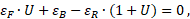
The block is described by the following kinematic relations:
where:
φB, φF and φR – turn angles at ports "B", "F", "R", respectively, rad
ωB, ωF and ωR – angular speeds at ports "B", "F", "R", respectively, rad/s
εB, εF and εR – angular accelerations at ports "B", "F", "R", respectively, rad/s2
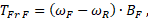
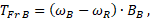
The torques at the block ports are related by the following ratios:
where:
TB, TF and TR – torques at ports "B", "F", "R", respectively, Nm
TFr F, TFr B – friction torques on the driving and driven shafts, Nm
BB and BF – coefficients of bearing friction on the driving and driven shafts, Nm·s/rad
ν – gearbox efficiency
A detailed description of the calculation methods for the variable efficiency in the gear meshing is given on page Gearbox efficiency simulation.
The block allows you to change the direction of the "B" and "F" ports for easy connection to other blocks of the model. If the block has both input ports, then the coupling equation is solved. A detailed description of the simulation approach for the gear ratios is given on the page Simulating transmission.
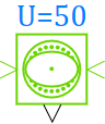
The gear ratio value U is displayed next to the block.
Inputs
Name
Description
Connection line type
R
Port for connecting the gearbox ring gear. The port is available when the "Ring gear rotation" property is activated
Rotary mechanics
Ports
Name
Description
Connection line type
V
Port for connecting the drive shaft (base). The port is input if specified in the"Input port" property, otherwise this port is output
Rotary mechanics
F
Port for connecting the driven shaft (following). The port is input if specified in the"Input port" property, otherwise this port is output
Rotary mechanics
Outputs
Name
Description
Connection line type
Q
Power losses due to bearing friction and gear meshing (efficiency)
Mathematical
Properties
Title
Parameter
Description
By default
Data type
Input port
Mod_Type
Allows you to specify the input ports. The possible values are: "B", "F", "B and F"
Time constant for solving the nonlinear algebraic equation, s
Tau
The time constant for solving the nonlinear algebraic equation. Used to solve the coupling equation. The property is available when selecting the input ports " B and F"
Allows you to define the friction model. The possible values are: "No loss", "Constant efficiency", "Variable efficiency on load", "Table data efficiency on load", "Table data efficiency on temperature"
The value of the power transmitted through the block, below which the efficiency is increased to achieve the stability of the numerical solution. The property is available when selecting the following friction models "Constant efficiency", "Variable efficiency on load", "Table data efficiency on load", "Table data efficiency on temperature"
Array of efficiency values. Efficiency values are calculated by linear interpolation depending on the load or temperature values. The property is available when selecting the following friction models: "Table data efficiency on load" or "Table data efficiency on temperature"