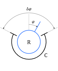
The block is designed to simulate backlash between two rotating bodies. The block is based on the Rotary position limiter block with identical stops located symmetrically relative to zero. The scheme of the limiter is shown in the figure (Figure 1).
Figure 1. Scheme of rotary backlash
In the figure (Figure 1), the following designations are adopted:
bodies C and R denote bodies connected to the mechanical ports "C" and "R" respectively
φ – relative angular position, rad
Δφ – backlash width, rad
The relative angular position and relative angular speed are calculated by the formulas:
where:
φC and φR – turn angles at the ports "C" and "R", respectively, rad
ω – relative angular speed, rad/s
ωC and ωR – angular speeds at ports "C" and "R", respectively, rad/s
Inputs
Name
Description
Connection line type
C
Port for connecting a conditionally fixed case (case)
Rotary mechanics
R
Port for connecting a conditionally moving shaft (rotor)