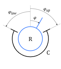
The block is designed to simulate a two-way rotary motion stopper. The stopper includes two stops limiting the relative angular position of the bodies connected to the block. Mechanical interaction with stops is simulated by viscoelastic forces. The stiffness and damping of the stops is set in the block properties. The scheme of the limiter is shown in the figure (Figure 1).
Figure 1. Scheme of rotary motion stopper
In the figure (Figure 1), the following designations are adopted:
case C and shaft R (rotor) denote bodies connected to the mechanical ports "C" and "R" respectively
φ – relative angular position, rad
φup and φlow – angular positions of the upper and lower stops, respectively, rad
The relative angular position and relative angular speed are calculated by the formulas:
where:
φC and φR – turn angles at the ports "C" and "R", respectively, rad
ω – relative angular speed, rad/s
ωC and ωR – angular speeds at ports "C" and "R", respectively, rad/s
Inputs
Name
Description
Connection line type
C
Port for connecting a conditionally fixed case (case)
Rotary mechanics
R
Port for connecting a conditionally moving shaft (rotor)