Key-7(t)
 |
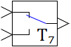 |
| Vector | |
| in the palette | on the schematic |
The block implements the function of the controlled key according to the following algorithm:
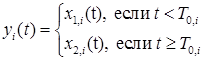
where x1(t), x2(t) are the signal vectors on the 1st and 2nd input ports; y(t) is the output signal vector; T0 is the input switching time vector with the block output.
where x1(t), x2(t) are the signal vectors on the 1st and 2nd input ports; y(t) is the output signal vector; T0 is the input switching time vector with the block output.
Inputs
- input1 - the first input of the block x1;
- input2 - the second input of the block x2.
Outputs
- output - block output, y.
Properties
- Setpoint values – vector T0.
Parameters
- Level - the current position of the key.
Note:
- By default, the block generates a scalar output signal.
- Named properties can be set as local model variables (submodels) in a programming language script, as global project signals using the Tools → Signals main menu item, or as external project signals using an attachable signal database.