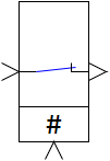
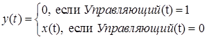
The block implements the function of the controlled key according to the following algorithm:
where x(t) is the input signal of the block (or signal vector), y(t) is the output signal of the block (or signal vector). The control signal enters the unit from above. During the calculation process the block image changes depending on the presence of the control signal: in normal position the key is closed, i.e. when the control signal is applied the key is opened:
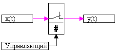
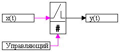
Figure 1. Control signal = 0
Figure 2. Control signal = 1
Inputs
Control - switching control signal;
x(t) - block input signal, x.
Outputs
y(t) - output signal, y.
Properties
none
Parameters
none
Note:
By default, the block generates a scalar output signal.