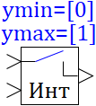
Integrator key
 |
 |
| Scalar | C | ST | |
| in the palette | on the schematic |
The unit implements the function of a controlled key for an integrating drive (such as an integrator or an inertia-integrating link) according to the following algorithm:
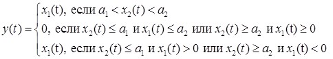
where x1(t) is the signal at the 1st input port; x2(t) is the control signal to the 2nd input of the block (from the output of the integrator located in series after this block); y(t) is the signal at the output port (at the input to the integrator); a1, a2 are threshold values (usually logical setpoints or, for example (conditionally), the positions of the lower and upper ends, respectively). ATTENTION: integrator gain ratio K > 0.
where x1(t) is the signal at the 1st input port; x2(t) is the control signal to the 2nd input of the block (from the output of the integrator located in series after this block); y(t) is the signal at the output port (at the input to the integrator); a1, a2 are threshold values (usually logical setpoints or, for example (conditionally), the positions of the lower and upper ends, respectively). ATTENTION: integrator gain ratio K > 0.
Inputs
- input1 - the first input signal x1;
- input2 - the second input signal x2.
Outputs
- output - block output.
Properties
- Minimum value — vector a1;
- Maximum value — vector a2.
Parameters
- Level - the current position of the key.
Note:
- The block converts only the scalar output signal.
- Named properties can be set as local model variables (submodels) in a programming language script, as global project signals using the Tools → Signals main menu item, or as external project signals using an attachable signal database.