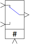
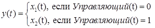
The block is vectorized and implements the controlled key function according to the algorithm:
where x1(t), x2(t) are the input signals of the block (or signal vectors), y(t) is the output signal of the block (or signal vector). The control signal enters the unit from above. During the calculation process, the image of the block changes, depending on the presence of the control signal: in the normal position, the key is placed to the first input, when the control signal is applied, the key is moved to the second input:
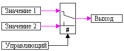
Figure 1. Control signal = 0
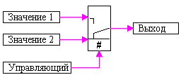
Figure 2. Control signal = 1The block is a submodel. To view the structure of the algorithm, right-click Actions → Enter to the submodel.
Inputs
Control - switching control signal;
Value1 - the first input signal of the unit, x1;
Value2 is the second input signal of the block x2.
Outputs
output - block output, y.
Properties
Setpoint values - a vector of threshold values of control signals K (usually logical setpoints) that determine the conditions for switching input signals to the output of the block.
Control signal type - selection of the type of control signals (Scalar or Vector).
Parameters
none
Note:
By default, the block generates a scalar output signal.
Named properties can be set as local model variables (submodels) in a programming language script, as global project signals using the Tools → Signals main menu item, or as external project signals using an attachable signal database.