НОР ИКП
 |
 |
| Vectorized | C | |
in the palette |
on the schematic |
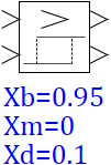
The block is a relay link with a deadband and two outputs, at the outputs it generates logical 1 or 0 according to the following algorithm: At the input to the unit, two signals are sent, which are compared to each other. If their difference exceeds the upper limit, the block forms a logical 1 at the first output. If the difference between the first and second input becomes less than the lower limit, then at the second output the block forms a logical 1. In other cases (if the difference is between the upper and lower limits, taking into account the value of the return zone), a logical 0 is formed at the outputs:
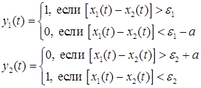
where x1(t), x2(t) are the input signals of the block; y1(t), y2(t) are the output signals; a, ε1, ε2 – the value of the return zone and the limits of the difference change (response limits). The block is a submodel. To view the structure of the algorithm, right-click Actions → Enter to the submodel.
where x1(t), x2(t) are the input signals of the block; y1(t), y2(t) are the output signals; a, ε1, ε2 – the value of the return zone and the limits of the difference change (response limits). The block is a submodel. To view the structure of the algorithm, right-click Actions → Enter to the submodel.
Inputs
- x1 - the first input signal;
- x2 - the second input signal;
Outputs
- upper setpoint - the difference is greater than the upper limit;
- lower setpoint - the difference is below the lower limit.
Properties
- Upper limit — the upper setpoint to which the difference in input signals is compared.
- Lower limit — the lower setpoint to which the difference in input signals is compared.
- Return zone — the value that is subtracted from the upper setpoint and added to the lower setpoint to form deadbands. The width of the deadband of the block is the same (both at the top and at the bottom).
Parameters
None